Please note that when I did this mod it was a spur of the moment thing and I didn't take down any measurements. Therefore I will do my best to make measurements from the finished product. I don't accept any responsibility for you damaging your Xbox, your mod or yourself! Also, don't attempt this mod unless you are confident you can do what is being described!
Also, apologies for the terrible grammar/ English etc. Normally I'd make an effort but I'm tired and cant be bothered :P
What
you will
need!
+++++++++++++
1)
Soldering
iron with
a 0.5mm
tip
2) Solder
(No shit?)
3) Flux
(optional
- I did
this without
any)
4) Desoldering
Braid
(Optional
- I also
didn't
need this)
5) Solder
Sucker
(What
I used
in place
of desoldering
braid)
6) Drill
and the
correct
size drill
bits (the
same size
as your
switches)
7) Center
punch
(Automatic
ones are
the best)
8) Ruler
and a
sharp
point
9) Dremel
or similar
tool with
cutting
bits
10) Files
(Oh yes,
there's
a lot
of filing
to do!)
11) A
long reel
of 0.5mm
insulated
wire.
12) 4x
Dual pole
single
throw
switches:
13) Pliers
14) Screws
that will
replace
the parallel
port nuts
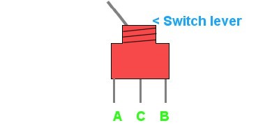
A
= Contact
is Off
when switch
is in
the position
B = Contact
is On
when switch
is in
the position
C = Contact
is the
common
terminal
Figure
1
--------
What
you will
be doing
++++++++++++++++
You will be taking off the dipswitches from the flash adaptor and soldering wires in their place. These wires will connect to switches which will be mounted on the front of the Xbox. On the top of the Xbox (just behind the DVD drive) you will be mounting the LPT (parallel) port and the actual flash adaptor.
What
to do
++++++++
First, take out the hard drive, cd drive, motherboard and power supply board (you don't need to remove the controller ports) - this is a required step as it prevents damage to the components and to remove obstructions)
Start
by desoldering
the dipswitches:
Peel back
the double
sided
adhesive
foam tape.
Heat the
dipswitch
contacts
one at
a time
and use
either
desoldering
braid
or a solder
sucker
to remove
the solder.
Once you
have gone
over all
8 contact
points
with a
little
force
you should
be able
to pull
the dipswitches
out of
the PCB.
If you
can, avoid
using
a screwdriver
as a lever!
I tried
this and
realised
after
I had
removed
the dipswitches
that there
is a trace
running
underneath
them (which
I almost
cut through!).
My advice
is if
you are
going
to use
a lever,
make sure
its plastic
and that
you stay
well clear
of traces.
Once the dipswitches are out you should have 8 nice little holes for the wires to fit in. Cut 8 lengths of wire (duh), each one should be about 40cm long. Strip the ends of the wire (you only need a very short length to go through the holes). Tin the wire (tinning is where you apply solder to the wire alone just to stop it from fraying and so solder sticks to it). If you have it, use flux on the solder point then thread the wire through the back of the PCB and solder on the front. A good solder job will not leave any blob behind on the contact and some of the solder will have actually gone through the hole to the other side. Repeat this 7 more times and that takes care of soldering to the PCB :)
The PCB should look like this when looking at it from the front side:
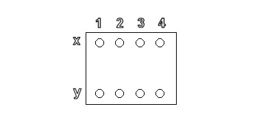
Figure
2
--------
The numbers represent the switch number and the o's below them are the respective terminal points.
Get a switch and solder one of the outer terminals (A or B - Figure 1) to switch 1 terminal X (Figure 2). Then solder the middle (common terminal) to switch 1 terminal Y (Figure 2). Remember, when using these switches the terminal A is on when the switch is flicked in the direction of terminal B and vice versa (See the switch diagram). This will help you when mounting the switches. Solder the other switches in exactly the same way (using the same terminal [A or B] as you did for the first switch). Once this is done try testing your switches to see if they work properly. If they don't go over your soldering again and make sure you're using the correct terminals (Remember, its one middle terminal and one outer terminal per switch).
Once they work, get your ruler out! Measure on the front of the Xbox about 1cm in and make a mark with your sharp tool. Then measure 1.5cm along to the right and make another mark, repeat this until you have 4 marks in total:
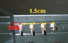
The red arrow is 1cm across, the yellow arrows are 1.5cm across each. Note, the red arrow starts from where the front of the Xbox becomes flat, not from right on the inside of the bend.
Once you have the hole positions marked out, use the center punch to make the mark bigger (not necessary but this stops the drill from skidding). The next thing to do is remove the metal shielding directly behind the plastic panel. Do this with a Dremel by cutting it away - be sure to remove enough so that the contacts of the switches don't short out against it!
Once you have done this, drill pilot holes with a small drill bit for each hole. You can then measure up the correct size of drill bit needed by holding the drill bit against the switch. Use the correct size drill bit to make the pilot holes the right size for the switches to fit through.
You're now ready to install the switches! Slot each switch through its hole (Remember to keep the order of 1 2 3 4 correct!) Now the tricky part - you need to keep the switches vertical while tightening them. Make sure that the switch is mounted as follows:
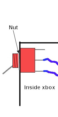
Note that the switch is installed so that the terminal nearest the top DOES NOT have any wire attached to it - this means that when the switch is down, it is off!
Ok - using your pliers, tighten up the nut on the threaded part of the switch. Make sure that the switch remains vertical! :) Do this for all 4 switches and you should be all done. On the lid of the Xbox, remove the tooth-like metal shielding which would fit directly above where you put the switches by snapping them off as these wont fit with the switches in place. This concludes the switch installation part of the tutorial. I should warn you, it gets harder from here.
Get the top cover of your Xbox, you will be making a hole on the top of it towards the back left corner (when viewed from the top). Look on the inside of the cover, when viewed from the front and from the inside, the hole you will be making will be at the top right - you will notice the metal shielding rises up around a ridge in this area. The easiest thing to do is to cut out the metal shielding in just this small area. The top right corner of the hole you want to dremel out is about 6cm from the side of the cover 4cm from the back - although I will leave deciding exactly where to place it up to you as mine actually catches against the DVD player.
Remove the nuts (with pliers) from the parallel port - the metal frame of the port will come off, don't worry!. Then, using a Dremel, cut through the PCB of the flash adaptor directly behind the parallel port:
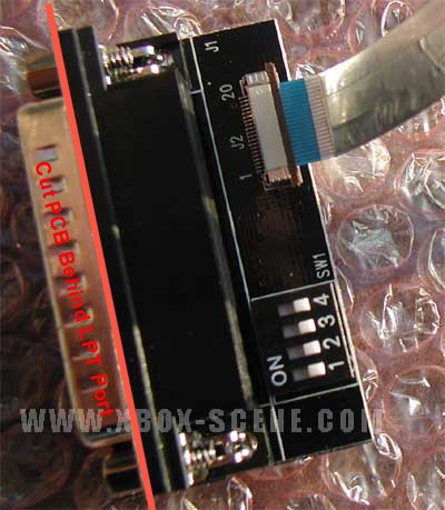
The reason you need to do this is to allow the parallel port to fit through the hole.
Dremel out a rectangle from the plastic lid about 4cm x 0.9cm (from the top right corner mentioned above) - this should be roughly big enough for the parallel port to fit through. You now need to do some filing to get the hole to the exact size required, believe me, this takes a long time to get perfect :/...
Once it fits in - drill holes (Using the metal parallel port frame as a guide) for your screws to fit into the parallel port. You should then be able to fit the parallel port into the hole and screw it in. If you used my exact measurements then you will have to mount the parallel port with the board nearest the back of the Xbox or you wont actually be able to close the case. The base of the actual parallel port will also foul against the edge of the DVD drive - this actually helps as it provides pressure to the port so it doesn't get pushed in when inserting the parallel cable.
You should now be able to put all of the components back into the Xbox and route the new wires safely around all of the components (try to avoid blocking the air flow with them!). Put the Xbox back together and if you did it all right - it should work. One thing to note - when putting the lid back on - make sure that none of the wires or the FCC cable gets crushed by the DVD drive. If the parallel port fouls against the DVD drive the case wont fit on very well until tightened up with the screws but it will leave a slight lump.
That about covers it all. Sorry about the vague areas - its very hard to describe without taking photos and I don't want to go back inside my Xbox to do so :P
If you have any questions just post them in the X2Pro forums!
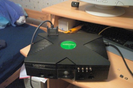
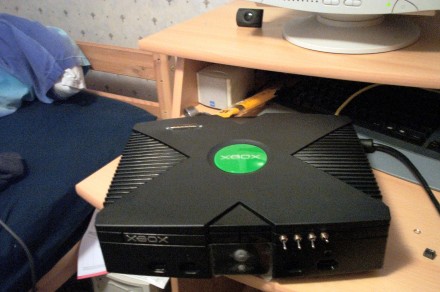
The final result (You should be able to work out the correct positioning of all the components from these photos)